
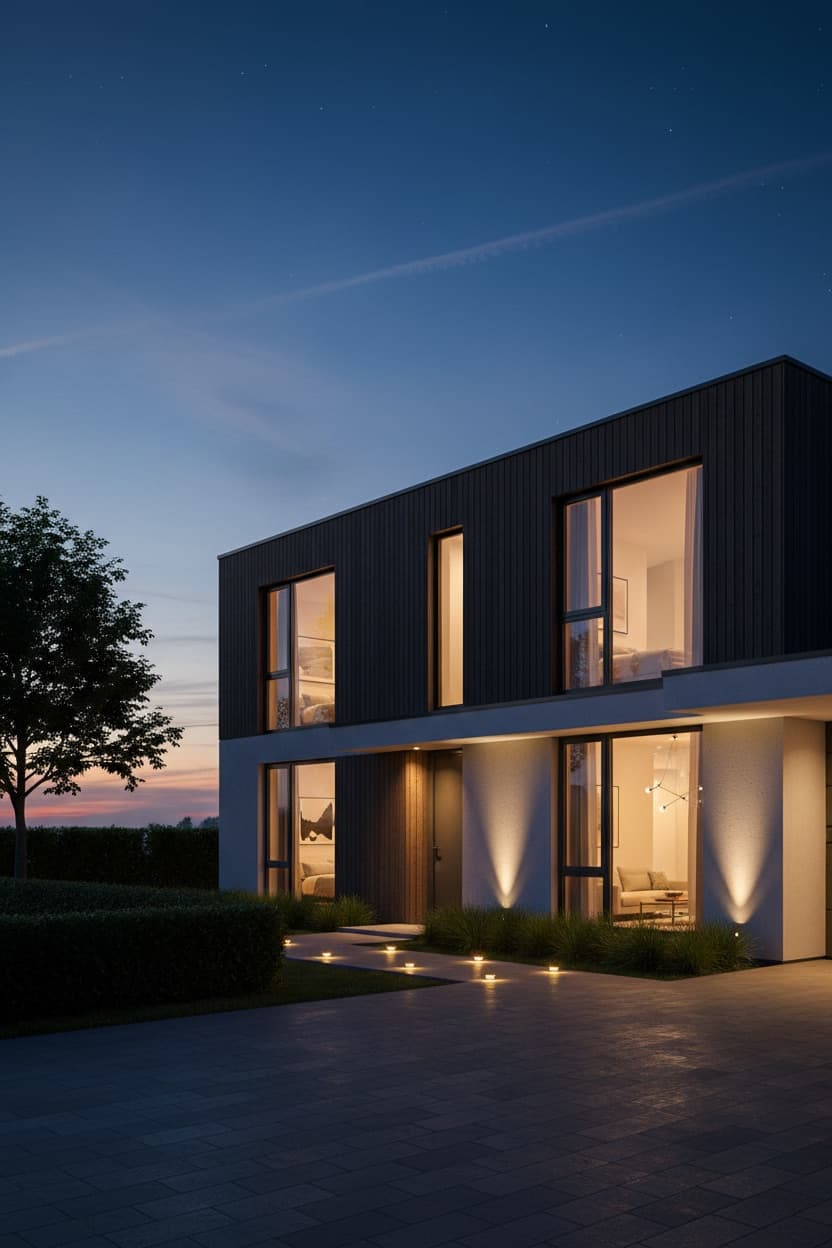
Most AI architecture prompts are image prompts. You describe a building, you get a picture of a building, and that picture is the end of the road — you cannot move a window, change a roof pitch, or walk a client through it.
GPT-6 Astra changes the shape of that problem. It operates Blender directly: writing Python to build geometry, rendering frames to inspect the result, and revising its own script where the render diverges from the brief. The output is not a picture of a building. It is a building — editable geometry you can open, adjust, and export.
These five prompts are written for that workflow. They are more demanding than the image prompts in our architectural drawing guide, and deliberately so: each one specifies a build process, an object hierarchy, and a set of checks the model must run before it stops.
What Changes When the Model Can Use Software
Three things matter once you are prompting an agent rather than an image generator.
It can check its own work. Astra renders a frame, looks at it, and compares it to the brief. That loop is the whole advantage — but it only runs if your prompt defines what "matching the brief" means. A prompt ending in "make it look good" gives the model nothing to test against. A prompt ending in a six-point checklist gives it a target.
Editability is not automatic. The default failure is a single merged mesh that renders beautifully and cannot be touched. Naming the objects you need — Walls, Roof, Glazing, Window_Frames — is the difference between a deliverable and a screenshot.
Scale must be established before anything else. With a floor plan especially, everything downstream depends on getting the scale right. Ask the model to derive it and state it back to you before it starts modelling, so you can catch an error at step one rather than after a full build.
Which of These Produce a 3D Model
Two of the five drive Blender and hand back editable geometry. The other three generate a picture. It is the single most important distinction on this page, so before anything else:
| Prompt | What you get |
|---|---|
| Building Photo to Architectural 3D Model | Editable 3D model — .blend + GLB, plus a render |
| Floor Plan to 3D Walkthrough Model | Editable 3D model — .blend + GLB, plus a render |
| Architectural Sketch to Render | A rendered image |
| House Elevation to Exterior Render | A rendered image |
| Day to Dusk Render | A rendered image |
The two 3D prompts need a ChatGPT tier with computer-use enabled, since Astra reaches Blender through its Python API. If yours returns a picture instead of a .blend, that is a tool-access limit rather than a problem with the prompt.
The Astra Archviz Prompt Formula
Every prompt below follows the same six-part structure:
1. READ — what to measure from the source before building anything
2. BUILD — what to model, with geometry fidelity as a hard constraint
3. STRUCTURE — which objects must stay separate and named
4. SURFACE — materials, then lighting, then camera
5. OUTPUT — file formats and render resolution
6. COMPLETION CRITERIA — the checks to run, and instruction to iterate
Part 6 is the one people skip and the one that does the most work.
1. Building Photo to Architectural 3D Model
The core Astra workflow: a photograph in, named and editable Blender geometry out, with a presentation render on top.
The prompt forces the model to state what it measures from the photo before it builds — storey count, floor-to-floor height, window grid, roof form — so an error in reading the reference surfaces immediately instead of propagating through the whole model. It also requires the model to say when it is inferring a hidden elevation rather than quietly inventing one.
Output: an editable 3D model — a .blend file and a GLB export, plus a hero render.
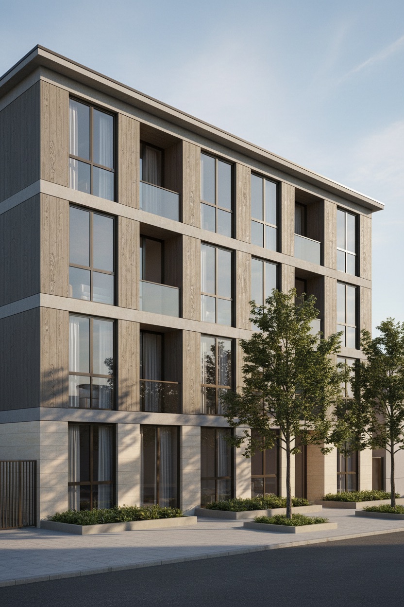
Generated output. Look at the vertical edges of the building — they run perfectly parallel to the frame rather than converging toward the top. That is a two-point perspective correction, and it is the single clearest tell separating an architectural render from a snapshot of a building. A camera tilted up to fit a tall facade makes the walls lean inward; architects correct it, so a render that does not looks amateur no matter how good the materials are.
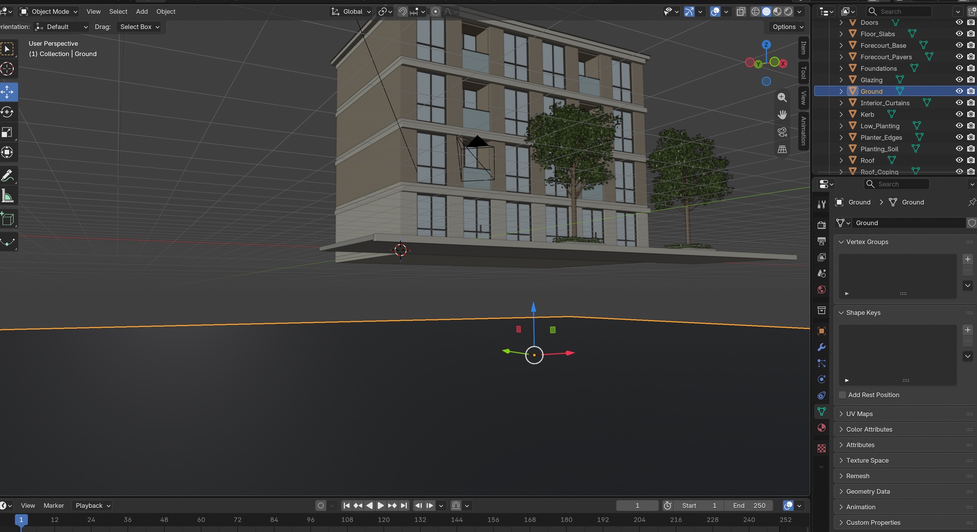
The actual output, open in Blender — and the reason the naming instruction earns its place in the prompt. Read the outliner down the right-hand side: Doors, Floor_Slabs, Glazing, Foundations, Kerb, Planting_Soil, Roof_Coping. Every one is a separate selectable object with its own material, so you can change the glazing without touching the walls, or delete the planting and keep the building. Drop the naming step from the prompt and the same view gives you one mesh called Object — it renders identically and is useless the moment you need to edit anything.
Attach your building photograph, select Astra, and paste this:
You are working as a 3D modelling agent with Blender open. Using the
uploaded photograph of a building, reconstruct the building as editable
3D geometry and produce a presentation render.

STEP 1 — Read the reference. Before modelling, state back what you
measure from the photo: number of storeys, approximate floor-to-floor
height, roof form, window grid and spacing, and the primary facade
materials. Work in real-world metric units. If the photo is a
three-quarter view, infer the hidden elevations symmetrically and say
that you are inferring them.

STEP 2 — Build. Model the whole building including the visible portion
of its site. Geometry fidelity is the hard constraint: preserve the
proportions, storey heights, window positions and roof pitch visible in
the photograph. Do NOT redesign, restyle, beautify or 'improve' the
building. If a detail is not visible, keep it simple rather than
inventing ornament.

STEP 3 — Keep it editable. Every element below must be a separate, named
object — not merged into one mesh: Walls, Roof, Glazing, Window_Frames,
Doors, Balconies, Ground. Apply a single material per named group. A
visually convincing single-mesh shell is a failed result.

STEP 4 — Materials. Match the materials visible in the photograph as
closely as you can identify them — set base colour, roughness and a
plausible bump or normal for each. No procedural noise standing in for
real material character.

STEP 5 — Scene. Ground plane with a paved forecourt with low planting
beds and two street trees. Lighting: clear morning light with the sun 35
degrees above the horizon from camera left, using a sun lamp with a
physically plausible angle plus a sky HDRI for fill. Camera: 24mm
three-quarter view from street level, at human eye height of 1.6m, with
the vertical lines of the building kept vertical — apply a two-point
perspective correction rather than tilting the camera up.

STEP 6 — Output. Save the .blend file, export a GLB, and render one hero
frame at the highest resolution Blender is set to.

COMPLETION CRITERIA — do not stop at the first render. Render the frame,
look at it, and compare it against the uploaded photo. Check: storey
count matches, window grid matches, roof form matches, no
interpenetrating geometry, no floating elements, vertical lines
vertical. Where the render diverges from the reference, revise your
script and re-render. Repeat until all six checks pass, then report
which checks you verified and list every named object you created.

Negative: single merged mesh, unnamed objects, redesigned building, invented
ornament, distorted proportions, tilted verticals, floating geometry,
interpenetrating walls, watermark, text overlay, low quality
▶ Try this as a fill-in template →
Best for: existing-building surveys, context models, retrofit and extension studies.
2. Architectural Sketch to Photorealistic Render
Takes a hand sketch, a SketchUp screenshot or a white massing model and renders it photorealistically.
The entire prompt is built around one constraint: this is a rendering job, not a design job. The geometry in your drawing is the design and it is fixed — massing, storey count, roof pitch, and the position of every opening. What the model is free to add is everything the sketch leaves out: real materials, honest glass behaviour, physically consistent light, site and entourage.
That separation matters more than any quality keyword you can add. Without it, the model treats your sketch as a mood reference and hands back a different, usually blander, building.
Output: a rendered image, not a 3D file. For editable geometry from a drawing, use Floor Plan to 3D or Building Photo to 3D Model instead.
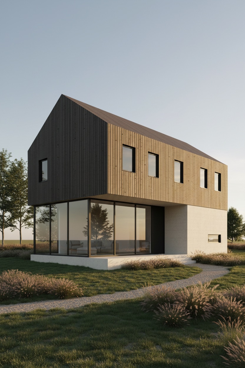
Generated output. The glazing is where this either works or collapses. Look at the ground floor: the glass carries a real reflection of the trees and sky across its surface and lets you see the furniture in the room behind it at the same time. Flat blue or mirror-silver glass is the default failure and it instantly reads as CGI — asking explicitly for partial reflection with interior visible behind it is what fixes it.
Attach your sketch, SketchUp screenshot or massing model, and paste this:
Using the uploaded architectural sketch, produce a photorealistic
architectural render of the same building.

THE HARD CONSTRAINT — this is a rendering job, not a design job. The
geometry in the source drawing is the design and it is fixed. Preserve
exactly: the massing and overall proportions, the number of storeys, the
roof form and pitch, the position and proportion of every window and
door opening, and the relationship between the building and its ground
line. Do not add storeys, move openings, change the roof, add ornament,
or 'improve' the composition. If part of the sketch is ambiguous,
resolve it in the simplest way consistent with the rest of the drawing
and say which reading you chose.

WHAT TO ADD — everything the sketch leaves out. Materials: vertical
charred timber cladding with a pale sandblasted concrete base and matte
black window frames, with real surface character — visible texture,
appropriate roughness, honest reflectance. Glazing: real glass behaviour
— partial reflection of the sky and surroundings, a hint of the interior
visible behind it, not flat blue fill. Lighting: late afternoon sun low
from camera right, long soft shadows, with physically consistent shadow
direction and soft contact shadows where every element meets the ground.
Site: a gently sloping lawn with native ornamental grasses and a gravel
path, scaled correctly against the building. Entourage: two small trees,
no people and no vehicles, kept restrained — supporting the architecture
rather than competing with it.

CAMERA — 28mm three-quarter view at eye level. Vertical lines stay
vertical: use a two-point perspective correction rather than tilting up.
Depth of field wide enough that the whole building reads sharp.

OUTPUT — a single render at the largest size the image tool supports. Do
not treat an exact pixel dimension as a requirement.

SELF-CHECK — before presenting, look at your render beside the source
drawing and compare: storey count, the presence and relative position of
every opening, roof pitch, and overall proportion. If something is
clearly off, regenerate once with that specific correction called out.
Judge this by eye — a rendered image is a new picture, not a traced
copy, so small differences are expected and do not need certifying.

Negative: redesigned building, added storeys, moved windows, changed roof form,
invented ornament, flat blue glass, tilted verticals, cartoon rendering,
sketchy output, watermark, text, low quality
▶ Try this as a fill-in template →
Best for: concept presentation, competition boards, turning early sketches into client-ready images.
3. Floor Plan to 3D Walkthrough Model
Converts a 2D plan or blueprint into a correctly-scaled, room-by-room model.
Scale comes first and everything else depends on it. The prompt asks the model to find the scale from dimension strings, a scale bar, or a known reference — a door leaf at 0.9m, a stair tread at 0.25m — and to state the derived scale and overall footprint before modelling. If the plan carries no dimensions, it says so rather than guessing silently.
Every room becomes a separate named object matching its label on the plan, and furniture is specified at real dimensions — a 3-seat sofa at 2.1m, a double bed at 1.4m by 2.0m. Wrong furniture scale is the fastest way to make an otherwise good plan render read as fake.
Output: an editable 3D model — a .blend file and a GLB export, plus a render.
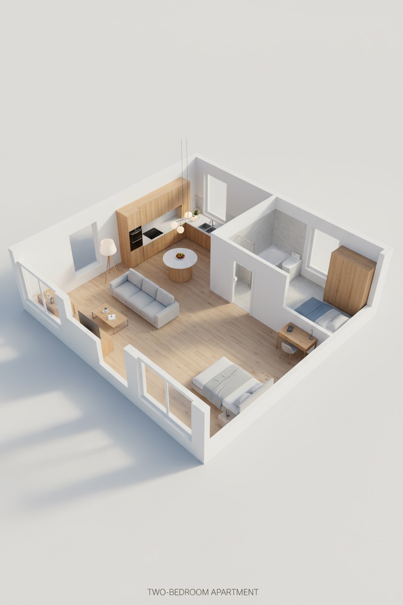
Generated output. Cover the furniture and this could be any scale at all — the sofa, the double bed and the kitchen worktop are the only things telling you how big these rooms are. That is why the prompt specifies furniture in real dimensions rather than by name. Ask for "a sofa" and the model will happily draw one that would need a nine-metre wall; ask for a 2.1m three-seat sofa and the whole plan snaps to a believable size.
Attach your floor plan or blueprint — ideally one showing dimensions or a scale bar — and paste this:
You are working as a 3D modelling agent with Blender open. Using the
uploaded floor plan, build a correctly-scaled 3D model of the dwelling
and render it.

STEP 1 — Establish scale first. Before modelling anything, find the
scale: read the dimension strings, the scale bar, or a known reference
such as a standard door leaf at 0.9m or a stair tread at 0.25m. State
the scale you derived and the resulting overall footprint in metres. If
the plan carries no dimensions at all, say so and assume a standard door
width, then proceed. Getting this wrong invalidates everything
downstream.

STEP 2 — Trace the plan. Extrude every wall to a floor-to-ceiling height
of 2.7m. Wall thickness: 300mm external, 100mm internal. Reproduce the
plan exactly — every room, every wall, every opening in the position
shown. Do not re-plan the layout, merge rooms, straighten walls or 'fix'
anything you consider awkward. Cut door and window openings at the
positions marked, using standard heights: doors 2.1m, window heads 2.1m
with sills at 0.9m unless the plan says otherwise.

STEP 3 — Name every room. Each room must be a separate, named object
matching its label on the plan: Living, Kitchen, Bedroom_1, Bedroom_2,
Bathroom, Hall, and so on. Walls, Floor, Ceiling, Doors and Glazing are
each their own named group. Nothing merged.

STEP 4 — Fit out. Furnish every room appropriately for its label. Every
item scaled to real dimensions — a 3-seat sofa is 2.1m, a double bed is
1.4m by 2.0m, a kitchen worktop is 0.9m high and 0.6m deep. Wrong
furniture scale is the fastest way to make a plan render read as fake.

STEP 5 — Materials and light. Floors: pale oak throughout, light grey
stone in the bathroom. Walls matte off-white unless the plan indicates
otherwise. Lighting: bright even daylight entering from two sides plus
warm practical lamps, with daylight entering through the window openings
in the positions you cut, plus warm practical lights where the plan
shows fittings.

STEP 6 — Output and view. Render a 45-degree cutaway dollhouse view with
the walls cut at waist height. Save the .blend and export a GLB.

COMPLETION CRITERIA — render, inspect, and verify against the plan: room
count matches, room adjacencies match, every door and window is in the
position shown, the footprint matches the scale you derived, and
furniture reads at plausible human scale. Revise and re-render until all
five pass, then report the derived scale, the overall footprint, and
every room object you named.

Negative: re-planned layout, merged rooms, wrong scale, oversized furniture,
missing rooms, doors in wrong positions, single merged mesh, distorted
geometry, watermark, text, low quality
▶ Try this as a fill-in template →
Best for: estate agent plans, dollhouse cutaway views, early layout testing.
4. House Elevation to Exterior Render
Turns a flat elevation drawing into a three-dimensional render — or restyles an existing house exterior with the structure left untouched. This is the one people reach for most: ChatGPT house exterior design, where you want new materials and colour on a house that stays the same house.
The prompt splits the job cleanly. Fixed: massing, storey heights, roof form and pitch, and the position and proportion of every opening. Free: materials, colour, roof finish, frame finish, entrance treatment.
The part that does the heavy lifting is depth. An elevation drawing is flat, and a render of it will look flat too unless you explicitly demand real projection — window reveals set back into the wall thickness, sills and heads projecting proudly, the roof overhang casting a shadow line on the wall below. Those cast shadows are what make the image read as three-dimensional rather than as a coloured-in drawing.
Output: a rendered image, not a 3D file — it will look three-dimensional, but nothing is editable afterwards. For real geometry use Building Photo to 3D Model.
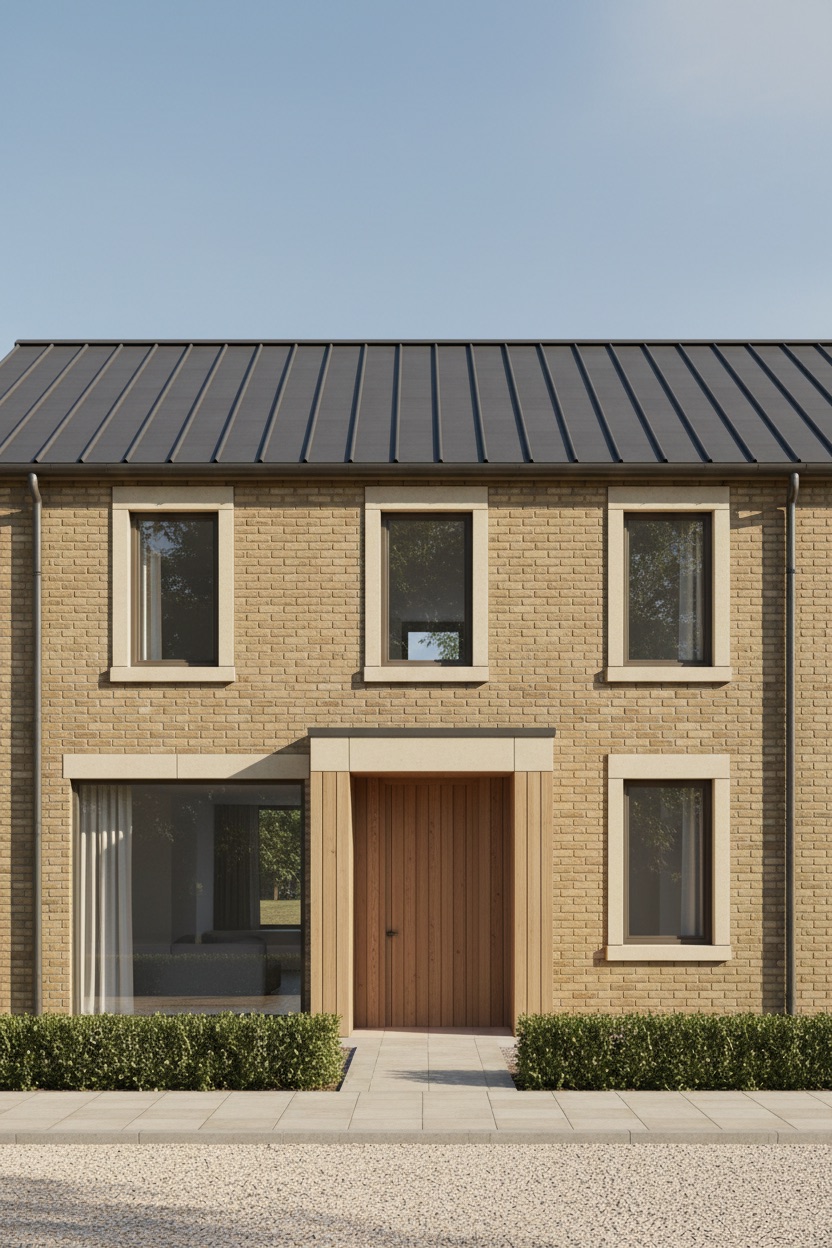
Generated output, and the best illustration of why depth matters. Find the thin dark line running along the wall just beneath the roof — that is the shadow cast by the eaves overhang. Then look at the stone sills: each one throws its own small shadow onto the brick below it. Those shadows are doing all the three-dimensional work. Render the same elevation without projection and you get a coloured-in drawing, not a building.
Attach your elevation drawing, or a straight-on photograph of the existing house, and paste this:
Using the uploaded elevation drawing, produce a photorealistic 3D
exterior render of the house.

WHAT IS FIXED — the structure. Preserve exactly: the overall massing and
footprint, the number of storeys and their heights, the roof form and
pitch, and the position, size and proportion of every window and door
opening. These are not yours to change. A restyled facade on the wrong
structure is a failed result.

WHAT TO CHANGE — the skin. Apply this exterior scheme: warm buff
handmade brick with pale sandstone sills and vertical cedar cladding to
the entrance bay. Colour: warm buff and pale stone with a dark grey
roof. Roof: dark grey standing-seam zinc with visible seam lines. Window
frames: dark bronze anodised, set deep into the wall reveals. Entrance:
a recessed porch with a timber-lined reveal. Apply materials with honest
surface character — brick with visible individual courses and mortar
joints, render with a fine float texture, timber with real grain
direction, stone with genuine coursing. Flat untextured colour fill is
the failure mode to avoid.

DEPTH — an elevation drawing is flat; the render must not be. Give every
element its real projection: window reveals set back into the wall
thickness, sills and heads projecting, the roof with its true overhang
casting a shadow line on the wall below, the entrance genuinely
recessed. The shadows those projections cast are what make the render
read as three-dimensional.

SITE AND LIGHT — Ground: a clipped low box hedge, pale gravel drive and
a paved path to the entrance. Lighting: clear late morning sun from
camera left at 40 degrees, with shadow direction physically consistent
across the whole facade and soft contact shadows at the ground line.

CAMERA — 35mm straight-on elevation view. All verticals kept vertical.

OUTPUT — one render at the largest size the image tool supports. Do not
treat an exact pixel dimension as a requirement.

SELF-CHECK — before presenting, compare your render against the source
drawing by eye: storey count, roof pitch, the position and proportion of
every opening, and the overall width-to-height proportion. If something
is clearly off, regenerate once with that correction called out, then
say briefly what you changed and what you preserved.

Negative: changed structure, moved windows, altered roof pitch, added storeys,
flat untextured colour, no window reveals, missing shadows, tilted
verticals, watermark, text, low quality
▶ Try this as a fill-in template →
Best for: elevation presentation, facade material studies, renovation before-and-afters.
5. Day to Dusk Architectural Render
The archviz money shot: a daytime render or photograph converted to blue hour with interiors glowing.
This one is a pure lighting change, and the prompt is mostly a list of things that must not move — building geometry, materials, camera position, composition, crop. Only light, sky and atmosphere change.
The craft is entirely in the exposure balance. A sky that still holds tonal detail, interiors glowing warm at around 2700K without clipping, and a facade sitting in soft ambient blue light that remains legible rather than silhouetted. The prompt also asks for varied interior intensity room to room — the living room bright, an upstairs bedroom dimmer, the hall a narrow warm slot. Uniformly lit windows are the tell that gives away a fake twilight shot.
Output: a rendered image, not a 3D file.
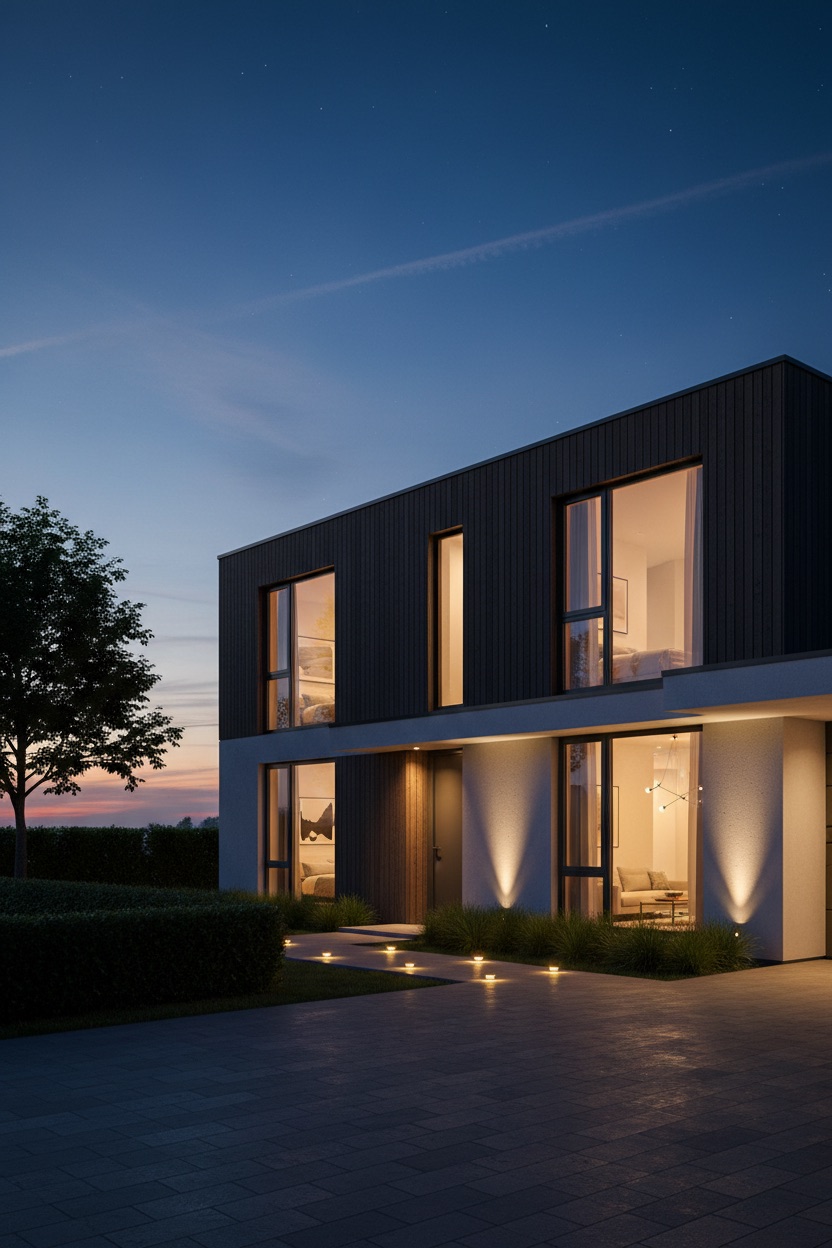
Generated output. Count the windows and notice that no two glow at quite the same brightness — the ground floor living space is brightest, the bedroom above it is dimmer and warmer, and the narrow slot by the door is dimmer still. Uniformly lit windows are the fastest way to make a twilight shot look fake, because real buildings are never occupied evenly. Note too that the sky still holds gradient and colour rather than going flat black; hold both of those and the shot works.
Attach your daytime render or photograph and paste this:
Using the uploaded daytime architectural render, convert the image from
daylight to dusk. This is a lighting and atmosphere change only.

WHAT MUST NOT CHANGE — the architecture and the frame. Preserve exactly:
the building's geometry, proportions and every material, the camera
position and angle, the composition and crop, and the position of every
window, door and architectural element. Do not re-render the building,
redesign any part of it, move the camera, or alter the landscaping
layout. Only the light, the sky and the atmosphere change.

THE SKY — replace the daytime sky with blue hour, roughly 20 minutes
after sunset. Deep blue gradient, darkest at the top of the frame and
warming toward the horizon where the last of the sun sits. A few streaks
of high cloud catching the residual light, first stars just appearing.
The sky must retain real tonal detail — never a flat black or a
blown-out gradient.

THE INTERIORS — this is what sells the shot. Every window that would
plausibly be occupied glows warm from within, around 2700K against the
cool blue exterior. Vary the intensity room to room so it reads as a
real building rather than a uniformly lit box: the living room bright
and inviting, an upstairs bedroom dimmer and softer, the hallway a
narrow warm slot. Through the glass, allow a suggestion of interior
depth — a ceiling plane, a wall, a hint of furniture — not flat orange
fill.

EXTERIOR LIGHTING — warm amber path lights along the walkway, two
uplights grazing the facade, a soft glow under the entrance canopy. Each
fitting casts a real pool of light with a visible falloff on the surface
it washes, plus soft contact shadows.

THE BALANCE — the entire craft of this shot is the exposure balance
between a sky that still holds colour and interiors that glow without
blowing out. Hold both. The facade should sit in soft ambient blue
light, still legible, its materials still readable — not silhouetted.

ATMOSPHERE — clear and crisp with a very light haze around the exterior
lights. Colour grade: cool blue shadows against warm amber light, deep
but never crushed blacks, saturated but believable.

OUTPUT — one render at the largest size the image tool supports, keeping
the source aspect ratio. Do not treat an exact pixel dimension as a
requirement.

SELF-CHECK — before presenting, compare against the source by eye:
camera position unchanged, building geometry and materials unchanged,
sky holding tonal detail, interior lights glowing without clipping,
facade materials still readable in the ambient light. If something is
clearly off, regenerate once with that correction called out.

Negative: changed camera angle, altered building geometry, redesigned facade, flat
black sky, blown-out windows, silhouetted building, uniform interior
lighting, flat orange window fill, daylight, watermark, text, low
quality
▶ Try this as a fill-in template →
Best for: marketing images, listing hero shots, planning submissions.
The Iteration Loop
Do not expect one prompt to produce a finished result. The workflow that actually works:
Run the prompt
  → Astra builds and renders
  → Look at the render against your source
  → Name the specific divergence ("roof pitch is too shallow,
     and the ground floor windows sit 400mm too high")
  → Astra revises the script and re-renders
  → Repeat
Specific corrections work far better than general ones. "Make it more realistic" gives the model nothing to act on. "The brick reads as flat colour — increase the mortar joint depth and add tonal variation between individual bricks" gives it a change it can make.
Limits Worth Knowing
Agentic runs are slow. A full photo-to-model build is not a chat response. Expect minutes, not seconds, and expect to iterate.
Geometry needs checking. Astra derives scale and proportion from images, and it gets both wrong sometimes. Verify against your source before anyone builds anything.
Nothing here is a construction document. These are concept and presentation tools. Dimensions are approximate, nothing is code-compliant, and anything heading for construction needs rebuilding in proper CAD or BIM.
Hidden elevations are inferred. A three-quarter photo shows two faces of a building. The other two are educated guesses, and the prompts ask the model to say so — but it is still a guess.
Frequently Asked Questions
Can ChatGPT Astra turn a photo into a 3D model?
Yes. Astra works as an agent inside Blender rather than as an image generator — writing Blender Python, rendering frames to inspect its own work, and revising where the render diverges from the brief. Given a photograph it can reconstruct matching geometry, apply materials, set up a camera and export a .blend or GLB. The critical thing to specify is that elements must remain separate, named objects, or you get a convincing single mesh that cannot be edited.
How is prompting Astra different from prompting for an image?
An image prompt describes a finished picture. An Astra prompt describes a job of work: what to build, which objects stay editable, what to output, and what checks to run before stopping. Astra will iterate, but only if your prompt defines what correct looks like.
What is the best ChatGPT prompt for architectural rendering?
The best ones separate what is fixed from what is free — geometry as a hard constraint, materials and lighting as the model's job. Without that separation the model treats your drawing as inspiration and redesigns the building.
Can ChatGPT produce construction-ready drawings?
No. Use it for concept visualisation, presentation and early massing. Rebuild in CAD or BIM for anything that gets built.